

")
")
")
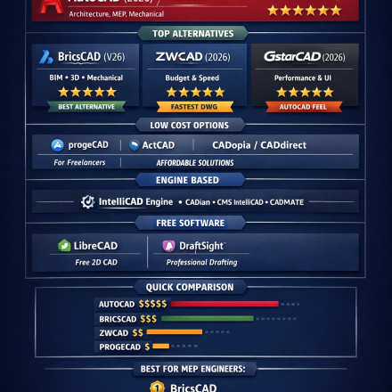
 + Official Websites")

 + PDF & Excel Download 2026")
")
")

: Power Consumption, Cost & Best Choice Guide")
")
")
")
")


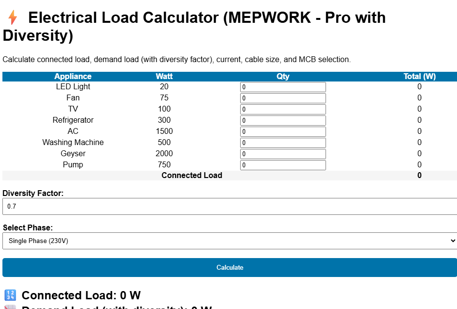
 + Free Excel Calculator 2026")
")
")
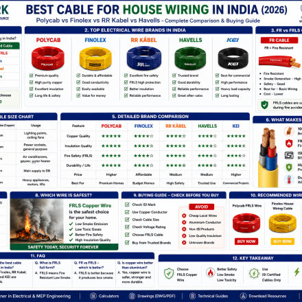
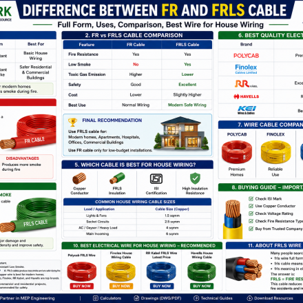
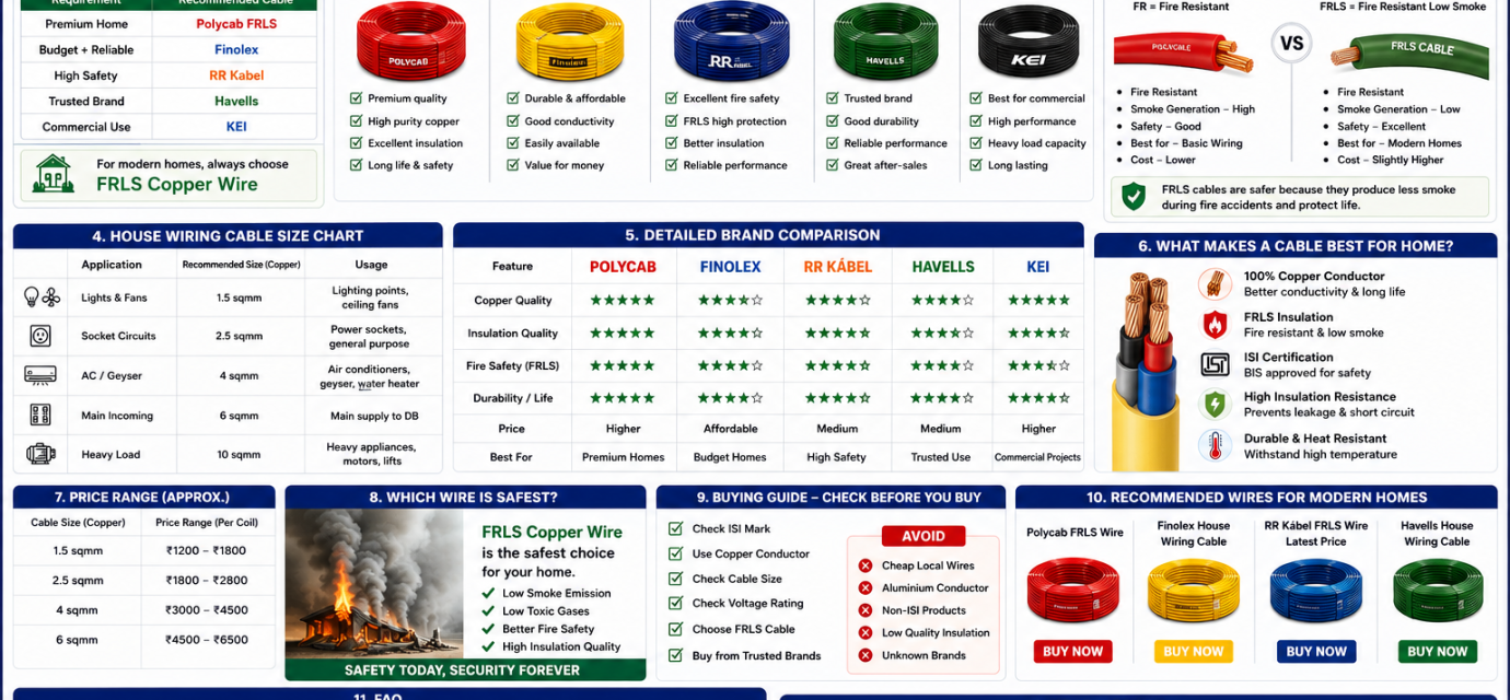
 | Polycab vs Finolex vs RR Kabel")
")
")
Control Module vs Relay Module in Fire Alarm Systems: Wiring, Working & Applications

Introduction
In modern addressable fire alarm systems, detectors identify fire hazards and the fire alarm control panel processes alarms. However, to interact with external equipment such as sounders, lifts, exhaust fans, access control systems, and Building Management Systems (BMS), specialized interface devices known as Control Modules and Relay Modules are used.
Although both modules are output devices, their functions, wiring methods, and applications are significantly different. Understanding these differences is essential for fire alarm designers, MEP engineers, installers, and maintenance personnel.
Why Are Control and Relay Modules Required?
Addressable fire alarm loops cannot directly operate every external device in a building. Many systems require an interface that converts fire alarm panel commands into usable outputs.
These interfaces are provided through:
- Control Modules – Provide a monitored 24V DC output.
- Relay Modules – Provide a dry contact (potential-free contact) output.
Selecting the correct module ensures reliable operation, proper supervision, and compliance with fire safety standards.
What is a Control Module?
A Control Module is an addressable output device designed to switch a supervised 24V DC power supply to external notification appliances.
Typical Applications
- Fire Alarm Bells
- Conventional Sounders
- Sounder Strobes
- Industrial Alarm Sounders
- Flameproof Sounders
Key Features
- Provides powered 24V DC output
- Supports output circuit supervision
- Requires End-of-Line (EOL) resistor
- Detects open and short circuit faults
- Usually requires external fire-rated 24V DC power supply
Working Principle
- Smoke detector senses fire.
- Signal reaches Fire Alarm Control Panel.
- Panel processes programmed logic.
- Control Module receives activation command.
- Module switches ON 24V DC output.
- Sounder or bell activates.
Because the module has a unique address, the panel can identify exactly which output is operating.
What is a Relay Module?
A Relay Module is an addressable output module that provides a dry contact rather than a powered output.
Relay Contact Configuration
- Common (COM)
- Normally Open (NO)
- Normally Closed (NC)
The relay changes state when activated by the fire alarm panel, allowing external systems to receive a trigger signal.
Typical Applications
- Lift Recall Systems
- Smoke Exhaust Fans
- Staircase Pressurization Fans
- Access Control Systems
- Public Address Systems
- Building Management Systems (BMS)
- Fire Dampers
- GSM Dialers
- MCC and Shunt Trip Interfaces
Key Features
- Provides potential-free contacts
- No EOL resistor required
- Generally not supervised
- Used for triggering external controllers
- Does not directly supply output power
How Relay Modules Work
Consider an exhaust fan smoke extraction system.
- Detector senses smoke.
- Fire Alarm Panel receives alarm.
- Cause-and-effect programming activates relay module.
- Relay contact changes state.
- Contactor coil energizes.
- Exhaust fan starts through its own power supply.
The relay module simply sends the command; it does not power the motor.
Control Module vs Relay Module
| Feature | Control Module | Relay Module |
|---|---|---|
| Output Type | 24V DC Powered Output | Dry Contact Output |
| Circuit Supervision | Yes | Usually No |
| EOL Resistor | Required | Not Required |
| External Power Supply | Required | Not Required for Contact |
| Main Application | Bells & Sounders | Lifts, Fans, BMS |
| Load Type | Notification Devices | Control Signals |
| Wiring Complexity | Higher | Simpler |
Addressability and Cause & Effect Logic
Both Control Modules and Relay Modules are addressable devices. Each module receives a unique address, allowing the fire alarm panel to control outputs individually.
Examples
- Activate sounders only in affected zone.
- Start smoke exhaust fan for fire floor.
- Recall lifts to ground floor.
- Release access-controlled doors.
- Trigger voice evacuation system.
This intelligent programming is known as Cause and Effect Logic, a critical feature of modern addressable fire alarm systems.
Common Applications of Control Modules
Fire Alarm Bell Control
Provides supervised 24V DC output to conventional bells.
Sounder Circuit Control
Used to activate sounders and strobes during emergencies.
Industrial Notification Systems
Suitable for flameproof and industrial-rated alarm devices.
Common Applications of Relay Modules
Lift Recall
Returns lifts to designated safe floor during fire emergencies.
Smoke Exhaust Systems
Starts exhaust fans for smoke extraction.
Staircase Pressurization
Activates pressure fans to maintain escape routes.
Access Control Integration
Unlocks emergency exit doors.
Public Address Systems
Triggers emergency voice announcements.
Fire Dampers
Activates damper control systems.
Building Management Systems
Provides fire status signals to BMS platforms.
Installation Best Practices
Install Modules Near Controlled Equipment
Reduces cable length and minimizes voltage drop.
Use Correct EOL Resistors
Always follow manufacturer recommendations.
Avoid Direct Heavy Loads
Relay modules should operate contactors or controllers, not large motors directly.
Use Protective Enclosures
Install modules inside ABS or weatherproof boxes where required.
Provide Clear Identification
Label every module with meaningful names such as:
- Lift Relay 01
- Exhaust Fan Relay 02
- Sounder Control Module 03
Proper labeling simplifies maintenance and troubleshooting.
Common Installation Mistakes
- Using relay modules where powered outputs are required.
- Using control modules where dry contacts are needed.
- Missing EOL resistors.
- Connecting high-current loads directly to relay outputs.
- Ignoring voltage drop calculations.
- Installing modules in inaccessible locations.
- Poor documentation and labeling.
Conclusion
The easiest way to remember the difference is:
Control Module = Powered Output (24V DC)
Relay Module = Dry Contact Trigger
Control modules are ideal for sounders, bells, and strobes, while relay modules are best suited for lifts, fans, BMS integration, access control systems, and other third-party equipment.
Proper selection, wiring, and programming of these modules ensure a reliable, intelligent, and code-compliant fire alarm system that improves life safety and emergency response performance.
Source: Technical notes and wiring concepts provided in uploaded document.
📢 Why Download from MEPWORK?
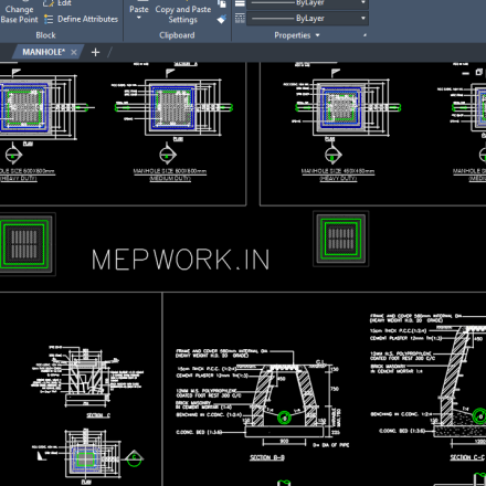
- Free DWG files
- Ready-to-use drawings
- Designed for engineers
- Updated as per industry standards
MEPWORK.IN is developed by an MEP engineering professional with hands-on experience in building services design and execution.
The platform is created to solve real-world engineering problems and provide practical tools for faster and more accurate project work.
Download free AutoCAD DWG files for MEP engineers including plumbing, HVAC, fire alarm, and electrical systems.
All drawings are ready to use and based on industry standards.
All resources are regularly updated as per latest standards (NBC 2016, IS Codes, NFPA, and 2026 industry practices).